These hour-long concerts feature a string quartet of leading BIPOC musicians performing family-friendly music, with a Q&A to follow each concert. These fun, informal, and intimate presentations are geared toward families and those who enjoy and want to learn more about classical music in an informal setting. Join us at venues across Los Angeles County this summer!
All education and outreach programs at LACMA are underwritten by the LACMA Education Fund and are supported in part by the Judy and Bernard Briskin Family Foundation, The Rosalinde and Arthur Gilbert Foundation, the William Randolph Hearst Endowment Fund for Arts Education, Alfred E. Mann Charities, The Ralph M. Parsons Foundation, Gloria Ricci Lothrop, the Flora L. Thornton Foundation, U.S. Bank, and The Yabuki Family Foundation.
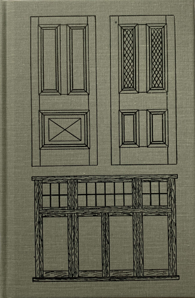
As the Industrial Revolution mechanized the jobs of the joiner – building doors and windows by hand – one anonymous joiner watched the traditional skills disappear and decided to do something about it.
That joiner wrote two short illustrated booklets that explained how to build doors and windows by hand. And what was most unusual about the booklets is that they focused on the basics of construction, from layout to joinery to construction – for both doors and windows.
Plenty of books exist on building windows and doors, but most of them assume you have had a seven-year apprenticeship and don’t need to know the basic skills of the house joiner. Or the doors and windows these books describe are impossibly complex or ornamental.
“Doormaking and Window-Making” starts you off at the beginning, with simple tools and simple assemblies; then it moves you step-by-step into the more complex doors and windows.
Every step in the layout and construction process is shown with handmade line drawings and clear text. The booklets are written from a voice of authority – someone who has clearly done this for a long time.
During the last 100 years, most of these booklets disappeared. Soft-cover and stapled booklets don’t survive as well as books. And so we were thrilled when we were approached by joiner Richard Arnold in England, who presented us with a copy of each booklet to scan and reproduce for a book.
Below is the introduction that Richard Arnold wrote for us. It is a family story that comes full circle and brings these booklets with it.
The story of how this book has come to be republished is a tale that goes back more than 100 years.
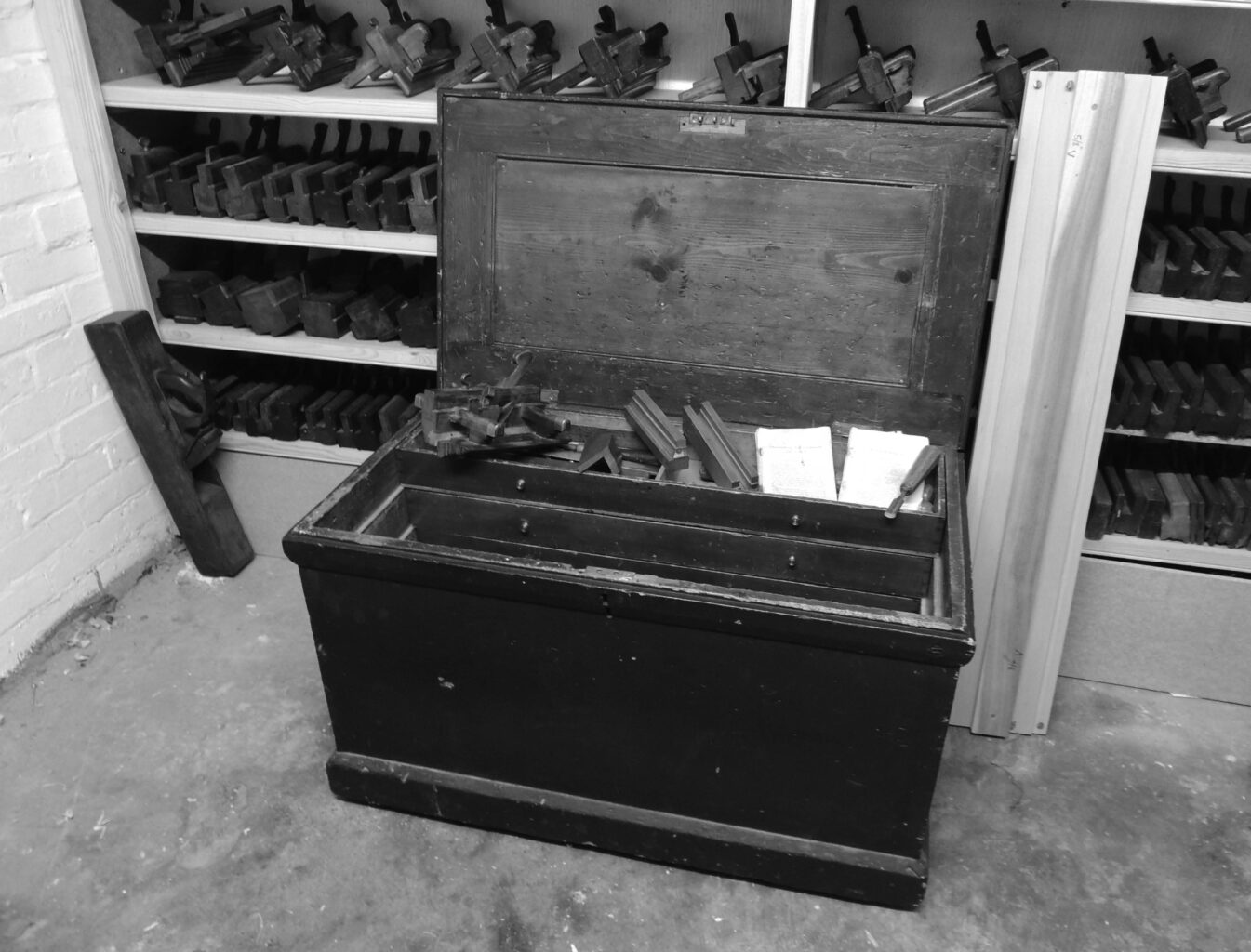
At the end of World War I, one of the lucky survivors of the trenches came home to England and started a new career as a carpenter and joiner. He was my grandfather, and his name was Cecil Incles.
Sometime during his apprenticeship, he managed to purchase a tool chest – complete with tools – that had belonged to a joiner by the name of G. Shelton. To date I have not been able to find any clues as to who Mr. Shelton was, but by dating the tools in his chest, it is reasonably safe to assume he assembled them sometime around the end of the 19th century. Judging by the types of tools in his chest it is obvious that he was a joiner, and amongst other things, he would have spent a lot of his time making doors and windows.
Lying in the bottom of the chest were two well-worn little booklets on door and window-making. They date from around 1910, so I think it is safe to assume they were first purchased by Mr. Shelton. I’m sure he found them helpful, as I presume my grandfather did after him.
On completion of his apprenticeship, my grandfather moved back to his birthplace and started work for a small building firm in a nearby market town. For the next 50 years, he worked as a joiner for the same company right up to his retirement. After his death in 1976, my father decided to hang on to my grandfather’s old tool chest, along with its contents, a decision that I am forever grateful for.
Two years after my grandfather’s death, I left school at age 16 with no clear idea of what I was going to do with my life. As luck would have it, the old building firm that my grandfather had worked for was looking for an apprentice to train in its joiners’ shop. So with hardly any woodworking experience at all, I found myself working under the watchful eye of “old Arthur.” Coincidently, Arthur had been one of my grandfather’s apprentices. My father had no great interest in woodwork, so he was happy to pass the tool chest and its contents to myself to use in my new career.
It is no exaggeration to say that this tool chest, and more importantly its contents, changed my life. Most of the tools in the chest were of no use in a modern working environment, but I became fascinated as to what they had been used for and how they were used. This led to a lifelong passion for anything to do with the history of woodworking, and the tools and techniques that surround the subject.
I soon discovered the two little booklets in the bottom of the chest, and I was surprised as to how relevant the information within them was to my everyday work. In time, they became my main point of reference whenever I’m working on doors or windows.
In the age where doors and windows were made by hand, the apprentice learned the basics under the watchful eye of his master. No one expected to have to record these skills; they were merely the basics, passed down from one generation to the next. But with the onset of the machine age and mass production, a lot of these techniques were soon lost.
The anonymous author of these booklets must have had the foresight to see this coming, and we should be forever grateful to him for recording his obvious years of experience making doors and windows as a joiner.
For years, I have recommended these wonderful booklets to fellow craftsmen, but sadly I could offer them no hope of finding copies for themselves because they rarely, if ever, came onto the open market. I would like to applaud Lost Art Press for making them available once again to everyone with an interest in keeping these traditional skills alive.
Richard Arnold November 2013 Northamptonshire, England
Chris Burden’s Metropolis II is an intense kinetic sculpture, modeled…
Perhaps the most dominant art form of the last 100 years, film has an important…
Tuesday Matinees
Enjoy concerts featuring leading international and local ensembles in programs o…
Art & Music,Jazz at LACMA,Latin Sounds
LACMA offers in-person art classes for kids, teens, and adults, offering the cha…
Random International’s Rain Room (2012) is an immersive environment of…
Rain Room
Artist Robert Irwin’s work in the last five decades has investigated perception…
Barbara Kruger’s Untitled (Shafted) features her distinctive use of advertising…
Band (2006) may qualify as Richard Serra’s magnum opus, representing the fullest…
LACMA’s Modern Art collection features primarily European and American art from…
LACMA’s Acquisitions Group and Art Council members share a deep affinity for the…
Art Councils,Acquisition Groups,Art of the Middle East: CONTEMPORARY,Asian Art Council,Costume Council,Decorative Arts and Design Council,LENS: Photography Council,Modern and Contemporary Art Council,Prints and Drawings Council
Welcome to the employment page of the Los Angeles County Museum of Art. To see a…
Jobs,Careers,Internships,Volunteer
Join museum educators, artists, curators, and experts for artist talks, virtual…
Create+Collaborate
In Golden Hour, over 70 artists and three photography collectives offer an aesth…
Established in 1967, the Conservation Center at LACMA supports the museum’s comm…
Barley, our temporary shop dog (he and his person are visiting this week).
Chris and I will be eagerly awaiting your woodworking questions this Saturday (April 19) from about 9 a.m.-5 p.m.
On Saturday morning, an “Open Wire” post will go live. If you have a question, all you have to do is type it into the comments and we’ll – eventually – answer (we fit in weekend computer time around bench time).
Readers with relevant info are also welcome to chime in. For example – we sometimes get asked things like, “Where near Flagstaff can I buy purpleheart?” We have no idea – so if you do, please do let the poor misguided* soul who wants to use purpleheart know where they can get it.
Get those questions ready. (And check out the “Open Wire” category in the meantime – there are lots of good questions and answers there already!)
The remaining Open Wire dates for 2025 are: April 19 June 14 August 9 October 25 December 13
– Fitz
*In all fairness, purpleheart is an excellent choice for a deck and will quickly turn gray/brown, thereby making it tolerable.
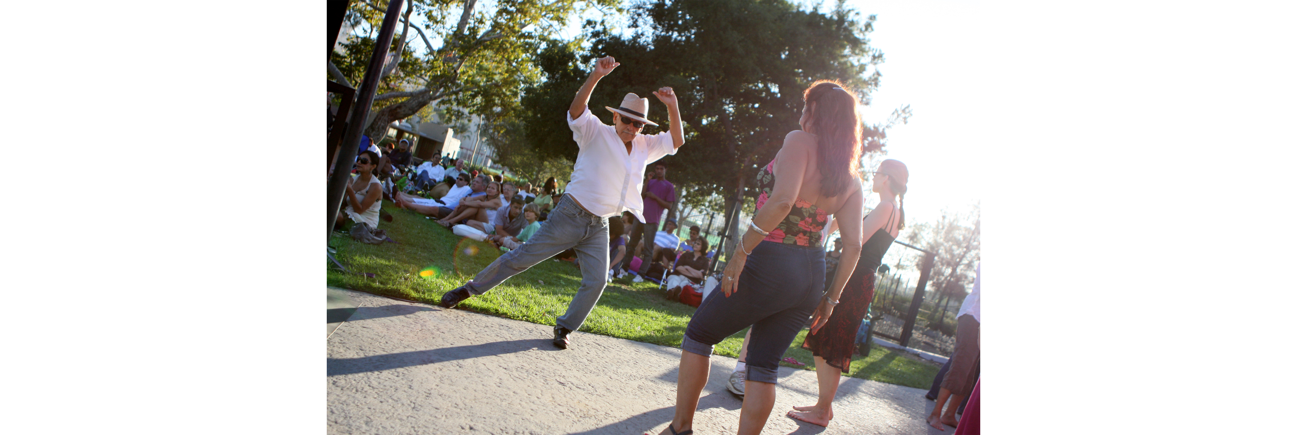
An Art fair is a booth-style marketplace offering a selection of artworks for sale, giving attendees the possibility to be key actors within the art world’s ecosystem. This club-like network encompasses individuals engaged in production, commission, presentation, preservation, promotion, documentation, critique, and the commercial aspects of art. It is bound by a shared conviction in the value and importance of Art.
Through buying and selling, Art fairs sustain the economic viability of artists and galleries while fostering an environment where art enthusiasts, collectors, and professionals can engage directly. This dynamic ecosystem plays a crucial role in shaping contemporary art trends, influencing both the market and artistic discourse. Art fairs are combining the role of a transactional space and a cultural institution that propels the art world forward.
The main actors involved in art fairs:
Organizers
Curators
Artists
Art dealers
Art critics
Art dealers
Collectors
Participants
Ordinary visitors
Are art fairs worth it?
Why do galleries pay a high fee and attend art fairs? Are art fairs good for artists? For example, to attend FIAC, the largest fair in France, costs around 15,000 EUR plus 20% tax for a 25-square-meter booth (the size of my kitchen). Not to mention the other associated costs.
1. Art fairs validate you as an artist
It’s hard to get into major international art fairs. Some art professionals would even call Art Basel Miami the Olympics of the art world. Usually, the organization sets a list of requirements such as being operational as a physical gallery for at least two years, having attended X number of similar art fairs, having several artists under the label, and the works must carry certain characteristics. To have exhibited at famous international art fairs like Art Basel Miami, FIAC, and in Spain, ARCO will bring you a reputation and respect in the industry.
2. They bring sales opportunity
Dealers are business owners; they make decisions based on financial outcomes. Dealers can make almost half of what they would make during the whole year by going to just five art fairs. Of course, these are just estimates and data from interviews with gallery owners. Regardless of the accuracy, it offers a snapshot of the economy behind art fairs. There is definitely a business drive behind paying tens of thousands of dollars to rent a booth and hire extra staff, not to mention the logistics!
3. They connect your art to the art world
ARCO alone can bring 100,000 art collectors to your booth, making it a great opportunity for exposure for networking. Art critics and journalists will be visiting the fair, generating some news pieces more likely to catch people’s attention. Also, internally, many artists will be more attracted to a gallery that brings their works to different fairs than the ones that don’t.
4. Be careful with the Fear of Missing Out (FOMO)
If you are not attending the larger fairs, you might be missing a lot of potential opportunities. In order to keep returning to large fairs, you need to attend smaller ones to be admitted. It goes into this “fair after fair” circle, and once you are used to it, you fear to change.
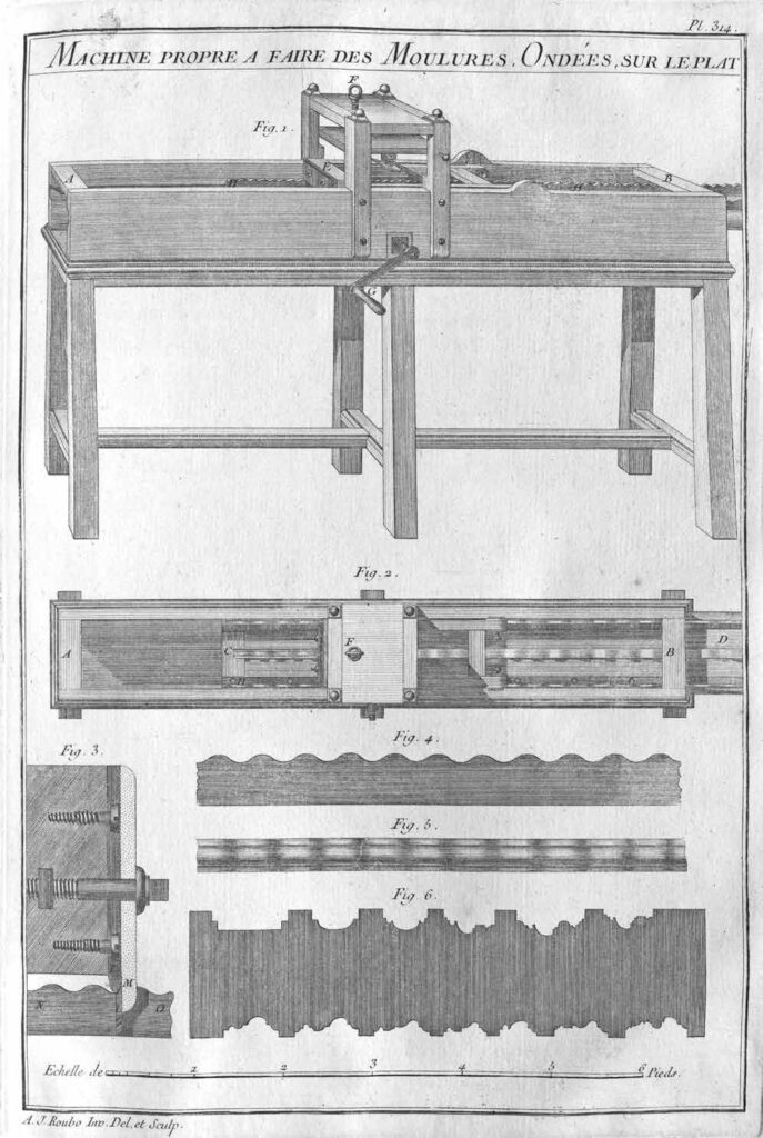
Plate 314. Machine Appropriate for Making Flat Wavy Mouldings
The following is an excerpt from “With All the Precision Possible: Roubo on Furniture.” This book is the result of more than a decade of work by an international team that produced the first English translation of the 18th-century woodworking masterpiece: “l’art du Menuisier” by André-Jacob Roubo. This translation covers Roubo’s writing on woodworking tools, the workshop, joinery and building furniture.
In addition to the translated text and color images from the original, “With All the Precision Possible: Roubo on Furniture” also includes five contemporary essays on Roubo’s writing by craftsmen Christopher Schwarz, Don Williams, Michael Mascelli, Philippe Lafargue and Jonathan Thornton.
The excerpt below details a machine that had gone out general use even before Roubo wrote the original text. However, there is no denying that the illustrations and explanation of the device are captivating. The details on it inspired Jonathan Thornton to recreate one of these machines and write an essay on it for “With All the Precision Possible.” A portion of the essay will be the excerpt for next week.
Description of the Machine commonly called the tool for waves, and the way of making use of it in different ways The machine that I am going to describe is the largest and the most complicated of all the cabinetry tools, which once were much used. Now they are not used much, since they are only used for works of applied wood [moldings] and they have, so to speak, combined all their science to veneer the wood properly. However, since this tool is ingenious, and you cannot find it anywhere, I thought I must include it here, in order to save it for posterity, supposing that this work succeeds.3
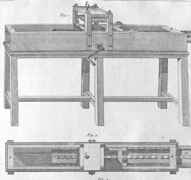
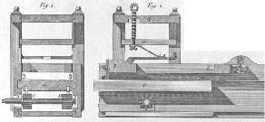
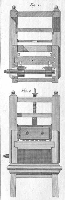
The use of the wave-cutting Tool represented in Fig. 1 is for cutting onto the wood wave-mouldings, or patterns, precise intricate repetitive designs, whether flat, on the face or even in both directions at the same time.
It is composed of a box from 7 to 8 feet in length, by one foot wide and 9 to 10 thumbs in height, exterior outside measurements. This box is open on top and at the ends, such that the distance between the two sides is retained only by cross-pieces A and B, Figs. 1 & 2, placed at two ends of the box, where they are assembled by mortise and tenon. At about the middle of the height of the box is placed a plank C–D, Fig. 2, about 2–thumbs thick, called a sommier [or platform, mattress; in similar machines for printing lithographs this is called the couch or the cooch]. This, for more strength, should be fit together at the ends and braced from below. This plank, or sommier [platform], is held in a groove in the two sides of the box (which should not be less than one–and-a-half thumb in thickness) and serves to hold the mouldings to be wave-cut, as I will explain later, and which you can see in Fig. 2, which represents the machine viewed from above.
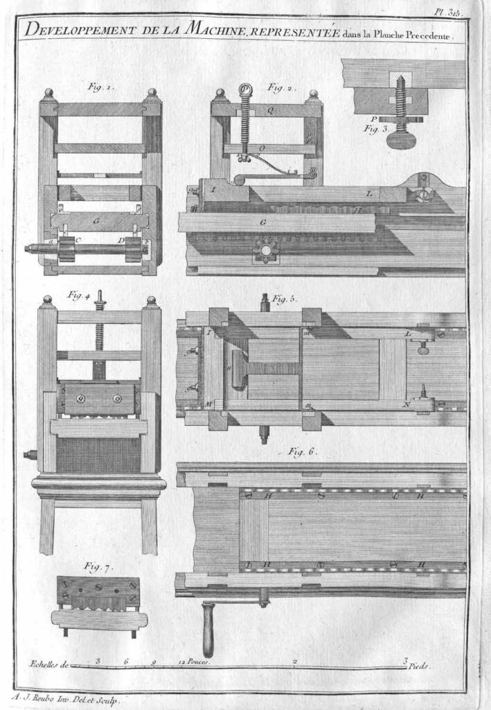
In the middle of the box is placed a square frame of about a foot in width, viewed from the side, and which extends from 9 to 10 thumbs above the box, to the sides of which it is attached with some screws, and in which it enters by tenon and a notch, as you can see in the evolution of this machine, represented in the following Plate [315] Figs. 5 & 6.
The width of this frame is determined by the width of the box, the sides of which the uprights of the latter are flush on the interior. It is in this frame that is placed a spring which presses on the toolholder [the cutterhead] E, Fig. 1. This spring is raised and lowered by means of the screw F, Figs. 1 & 2.
The whole machine is held on a base of a solid construction and widened [splayed] in the form of a trestle to give it a better footing. The height of this base should be from 2 feet 8 to 10 thumbs, so that is has about 3 feet in height from the axis of the crank handle G to the ground. This is the most comfortable height for the person who turns this crank handle to have all his strength, whether raising or lowering it.
There are in this machine two movements: one is horizontal, which is done by means of the handle G, Fig. 1, which by making the pinion turn placed in the interior of the box, moves the sommier A–B, Fig. 2, and consequently the work which is held above.
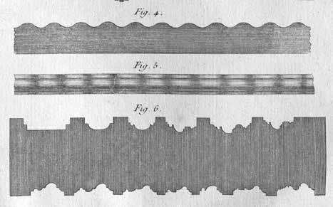
The other movement is vertical, downwards, and depends on the first. The rod, or wave guide/ channel H–H, Figs. 1 & 2 [Plate 315], which is held on the sommier, moves therefore with the latter, is raising the tool-holder F, Fig. 1, left, which then lowers immediately by itself, both by its own weight and by the pressure of the spring placed above. See Fig. 4, which represents a wave channel the size of the execution [ full-size/scale] Fig. 5, [which] represents a moulding completely wave-formed, according to the sinuosity of the wave channel in Fig. 4. Also see Fig. 3, which represents the cross-section of the tool-holder, which I will describe here later.
Fig. 6 represents a cutting blade viewed with different profiles, as large as the execution [ full-size/scale].
Figures 1 & 2 of this plate represent one of the transverse cross-sections of the machine, taken at the location of the pinions and the other the longitudinal cross-section of the same machine, so as to better understand the details of its construction and the mechanism of its operations.
Axis A–B, should be placed in the copper collars, a, b, so that they turn more easily. One should note at one of the sides of the box [is] a squared opening capable of letting pass pinions C–D, supposing that it is necessary to remove the axis outside. Pinions C–D, engaged in the toothed rack c, d, Fig. 1, and E, F, Fig. 2, which are embedded on the underside of the carriage [platform] G–G, same Figure, about 9–lines deep, and are held there by pegs, placed together in the sides of the latter, observing that the toothed racks are well positioned vis-a-vis the other, so that the two pinions C–D, Fig. 1, are contacted equally by the racks [platform] above. However, as it can happen that the teeth of the pinions are not well positioned vis-a-vis the other, one would do well, after having stopped/blocked one of the toothed racks, not to attach [secure] the other until after verifying that it fits well with its pinions, so as to be able to set it back or advance it as necessary.
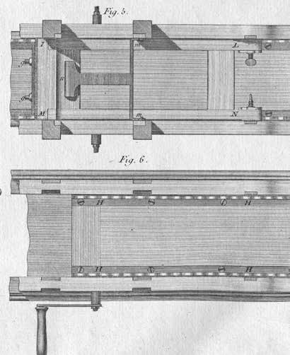
Plate 315. The Development of the Machine Represented in the Preceding Plate
These racks can be made of iron or copper, which makes no difference for the machine, however it would be good that they be made of copper, given that the rubbing of two different metals is smoother and wears less than if the two pieces, that is to say, the rack and pinions, be of the same metal. [See Plate 314.]
The rods or wave conduits [channels or guide rails for the work piece] e, f, Fig. 1, and H, H, Figs. 2 & 6, should be also made of copper, and they should be bent at a right angle to have the ability of attaching them with screws on the carriage [platform] in which they are notched in all their thickness, as one can see in Figs. 1 & 6.
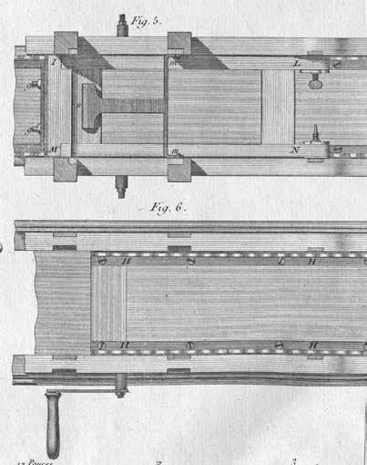
When you put these [wave] channels on the platform, you must pay the greatest attention that the guilloche [pattern] be not only fit well together, but also that they match at the same point of their contour with the contact of the tool-stand which bears on top of it, as you can see in Fig. 4. This represents the machine viewed from the end, and even better in Fig. 7, which shows the toolstand [tracing and cutting head] where you have removed the cheek [ fence] which holds the iron in place, as I will explain later.
The tool-stand is a frame I–L, M–N, Figs. 2 & 5, of about 2 feet in length, by a width equal to the interior of the box, less the necessary play to prevent any rubbing, which you avoid by diminishing the thickness of the uprights in the entire length, and reserving there some heels at the ends, so that the frame is held against the sides of the box, and cannot get out of place when you move it.
The frame of the tool-stand is attached at the sides of the box by means of two threaded bolts, represented in Fig. 3, half as large as executed here, where the extremity o ends in a cone, and bears on a copper collar embedded in the side of the box.
This screw is held in place in the frame by a nut placed in the middle of its thickness, normally. To prevent the movement of the frame so that it does not turn the screw, you put a counter-screw P outside, which you tighten against the frame, which prevents the screw from making any movement. See Figs. 3 & 5.
As it is sometimes found where it is necessary to lift the point of the movement of the toolstand, you pierce many holes in the copper collar attached to the side of the box, as I did in Fig. 2.
At the other end of the tool-stand, that is to say, where the cutting iron is secured/fitted, the cross-piece I, Fig. 2, should be very strong and assembled with a cover from above so as to present a uniform surface all along the length, which is the width of the tool-stand. Then you apply from above a piece of iron attached with some screws with countersunk heads, of a length equal to the width of the latter. And you make it overlap by about 5 or 6 lines at both ends, to make two frets that bear on the wave pattern [channels], and you make a notch in the middle of this piece of the size of the iron for positioning the cutting iron of the tool, as you can see in Fig. 7.
This iron is held in place by a cheek [ fence] (whether of iron or copper, either is equal), that you hold in place by means of two square-headed screws, g–g, Figs. 2, 4 & 5, where the nut is placed in the thickness of the cross-piece of the frame. See Fig. 3 of Plate 314, where I showed the cross-section of the tool-stand, with the contact I, the iron L, and the exterior cheek [ fence] M, which comes down as low as possible, that is to say, just to the bottom of the part the most hollowed of the latter.
The bottom of contact I [Plate 314] should be the thinnest possible (without however being a sharp edge), so that it follows well all the contours of the wavy pattern N–O. You must take great care that the point of contact for the fret be in the same direction as the iron cutting edge [both bevels are in the same direction], as I noted in this figure, so that the movement of the tool (which is made in describing an arc, where the center is found at the end of the frame) be less noticeable. I have partially remedied this by lengthening the point of the center of movement as much as has been possible.
The weight of the tool-stand should be almost sufficient to make the cutting iron bite into the surface of the wood workpiece. However, one must always put a spring there, both for augmenting the weight of the tool, supposing that it be necessary, and preventing it [ from] jumping around.
This spring h–i, Fig. 2, does not bear immediately on the tool-stand, but on a lever where its arms are loosely attached to the uprights of the movable frame of the box at m, Figs. 2 & 5.
The other end bears on the cross-piece of the tool-stand at n, which augments at the same time the strength and the elasticity of the spring, where the upper part is held below the small shelf O, Fig. 2, with screw P, where the nut is placed in the top of the frame Q. This screw serves, as I already said, to increase or diminish the pressure of the spring. The small shelf O through which passes the lower end of the screw, serves nothing but to hold it in place, and to press the heel o of the spring. As this small shelf is movable, you hold it from the opposite side of the screw with two pins, which you place across the uprights of the frame, as indicated by points p–p.
I made the head of the screw P in the form of a screw-eye, so that one cannot tighten it or loosen it by simply touching it, and so that you have need for a little pry bar or crank handle to do it. Those who approach the machine while it is adjusted cannot disturb anything there by simply touching it.
It is for this same reason that I prefer the screws with squared heads for closing the cheek [ fence] of the tool-stand, because a wrench is necessary to move these sorts of screws. You can eliminate their access from everyone’s hands, and consequently prevent anyone from changing anything on the tool.
As to the manner of using this machine, it is very simple. You begin by planing some wooden strips to the thickness of the profile that you have chosen, and the projection of the waves. This being done, you put in the tool-stand a smooth iron, which you adjust to the height equal to the projection of the moulding. You hold the strip on the platform, by means of little iron points placed [on the latter by equal distances from each other], and you make the machine move by turning the crank handle, which advances the platform forward. Consequently, the strip that is attached to the platform, after having passed many times under the smooth iron, is found to be wavy on its surface.
When the strip is thus finished, you remove the smooth iron, and you substitute the one that is shaped with a profile, and you begin the operation again, just until the iron is not cutting the wood any more, and consequently the moulding is perfectly finished.
You must take great care before running the moulding to verify that the wooden strip is placed truly parallel, which you know by making it pass the entire length under the blade that you hold elevated above. You should secure the strip on the platform only after having taken this precaution. You must also note that the pins that you place in the platform to hold the mouldings are positioned in the middle of their width [thickness of the moulding stock], and that they do not project enough to be able to meet the blade and cause any breakage, which you must take great care to avoid.
The blade of the waving tool is always placed perpendicular to the workpiece, which makes it scrape enough to cut, which cannot be otherwise, given that if you slant it in the normal way with moulding planes, it would scratch/drag on the wood as it comes against the grain, which happens at each undulation. What’s more, the blade thus slanted will no more be found in the same direction in all parts, which you must avoid as much as possible.
Since you can make many different blades, you must pay attention that they be all the same width, so that they completely fill the notch made in the piece which makes the cuts. You must also pay attention that they are all the same thickness, and that this thickness be considerable, to better resist the force of the wood in passing below.
The handle with which you move the waving tool can be placed to the right of the machine, as in Fig. 6, or to the left, as in Figs. 1 & 4, which makes no difference.
Each of these ways placing the handle has its advantages and disadvantages. If you place it to the right, which is the most natural way (since you made some effort pushing it), you cannot see the work well, behind which you position yourself. If on the contrary you place it to the left, you see the work clearly, but you are required to turn the handle in reverse. That is why, in order to eliminate these two inconveniences, I believe it would be better to position the two ends of the axis so that each one can receive a handle, like in Fig. 5, such that you can use it as you judge appropriate, whether on the right or on the left, or even from both sides at the same time.
3 It has not been possible to find a surviving wave-cutting Tool to make a good description of it. I have had only two iron blades, sold with other scrap metal which have nevertheless been very useful for fixing certain sizes, that I could not have known except for the description that Mr. Felibien made of this tool, which is otherwise very succinct, but imprecise, such that it could serve only to give me an idea of this machine, which I have then arranged in such a manner that it appeared to me the most likely. It has been greatly wished that those who have described this Machine in the Encyclopedia [of Diderot] had done something other than copy Mr. Felibien, instead of adding to the obscurity and inexactitude, as they have done. It would have been very useful to the public, and in particular to cabinetmakers, for whom they would have saved, or better said, presented one of their principal tools.
It’s worth noting that this year’s ARCO has faced criticism, as is often the case, with two main points standing out:
Nothing really new
Firstly, there’s a noticeable lack of innovation. After almost half a century, things can start to feel repetitive. While consistency is reassuring, there’s a shortage of new ideas, media, and experimental endeavors. Despite being a trade show where sales are paramount, nurturing creativity and pushing boundaries is essential.
Costly
Secondly, accessibility has become a significant concern. With ticket prices soaring to 52 EUR per person at the ticket office and 44 EUR online (22 for students), it’s becoming increasingly inaccessible to those from more modest backgrounds. This high cost alienates potential art lovers and collectors, hindering the growth of the art community. Many online commenters have voiced their discontent with this issue.
The Rise (and Trap?) of Textile Art
Textile art is gaining traction at art fairs, often championed by women artists. They use weaving to revive traditional techniques or elevate craft as an art form. While the art world pushes for inclusivity, women are often confined to craft-based media. The trend reinforces a divide—textiles for women, painting and sculpture for men. How many male artists do you see weaving? Almost none. Instead of breaking barriers, this trend might be reinforcing them.
Women make up 40% of the artists at ARCO
A respectable percentage. But dig deeper: women dominate in the Opening section, which is dedicated to young galleries. Emerging platforms seem to embrace change faster than the establishment. Will this momentum carry over, or will the traditional market gatekeepers keep the balance lopsided?
The market still plays by old rules
Money speaks. The highest-priced pieces at ARCO remain in the hands of dead male giants from a long time ago. Joan Miró’s “Head with Three Hairs Facing the Moon” commands €1.6 million. A still life by Juan Gris, “Pipe et Paquet de Tabac” sits at €1.25 million.
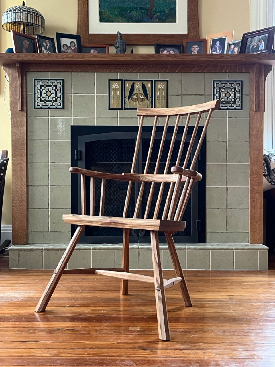
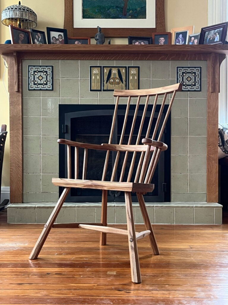
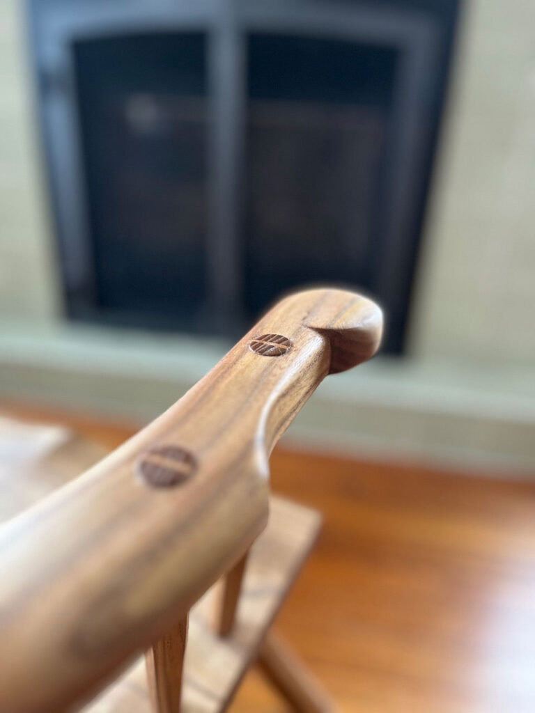
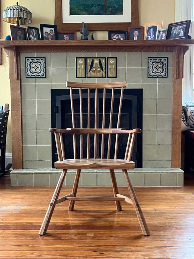
This comb-back stick chair is built entirely in American red elm, with the seat, arm and comb made from figured red elm, some of the most difficult wood I have ever saddled.
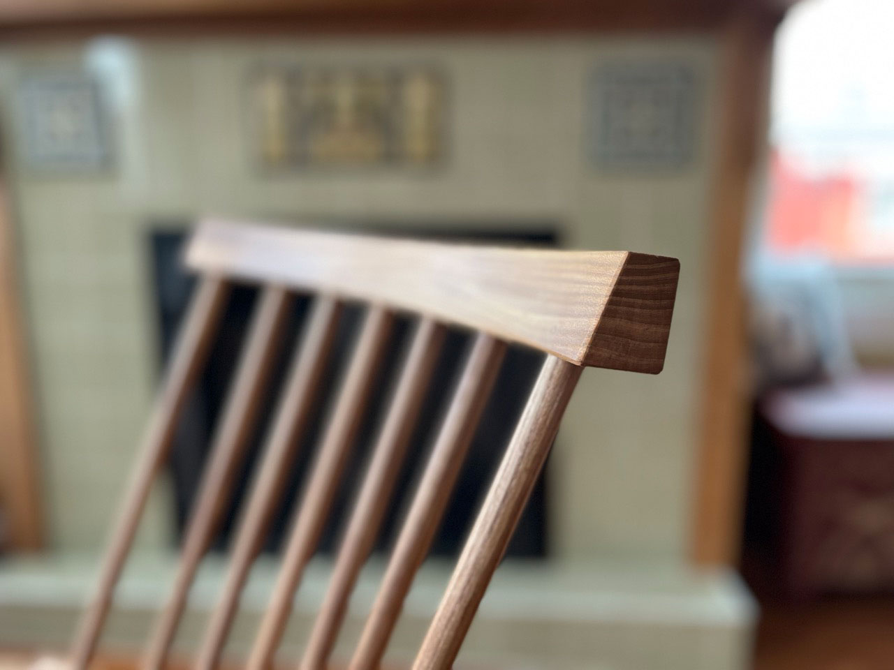
The chair is raked back for lounging, reading or sitting by the fire. The chair’s features heavily shaped arms, tapered octagonal stretchers and slightly proud and burnished tenons throughout.
I’m offering it for sale via a silent auction. The highest bid includes crating and shipping the chair to your door anywhere in the lower 48 states of the U.S. With no additional fees or charges. Details on the sale are at the bottom of this entry. First, some notes about the chair.
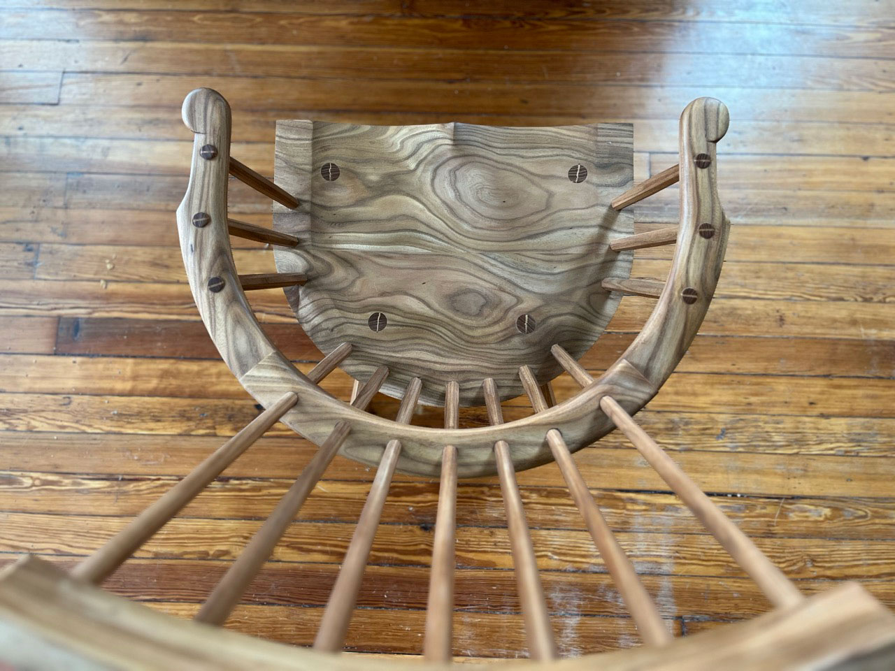
The chair is made from red elm, which is my favorite wood for chairmaking. The wood is strong, fairly lightweight and has a difficult interlocked grain that prevents the parts from ever splitting. The chair’s sticks are shaved and left octagonal. All the tenons are cut slightly proud and burnished. All the chair’s joints are assembled with animal glue, which is reversible, and wedged with hickory wedges selected for arrow-straight grain.
The seat is tilted 6.6°, with the chair’s back tilted 28° off the seat. The seat is 16-3/4” off the floor, making it comfortable for most sitters. The chair is 38-3/4” tall overall.
The chair is finished with a soft wax finish that I make here in our workshop. It offers a low lustre and looks better the more you use the chair. The finish isn’t terribly durable, but it is easily repaired (just add more soft wax).
Like all my chairs, I make them as best I can, but most of the work is by hand. So you will find an occasional stray tool mark or tiny imperfection. These are not left intentionally, but they are the result of hand work.
How to Buy the Chair
The chair is being sold via a silent auction. If you wish to buy the chair, send your bid via email to lapdrawing@lostartpress.com before 3 p.m. (Eastern) on Wednesday, April 24. Please use the subject line: “Elm Chair.” The opening bid is $500. In the email please include your:
Bid
U.S. shipping address
Daytime phone number (this is for the trucking quote only)
If you are the highest bidder, the chair will be shipped to your door. The price includes the crate and all shipping charges. Alternatively, the chair can be picked up at our storefront. (I’m sorry but the chair cannot be shipped outside the U.S.)
Wynwood Miami – Collaboration with Gera Lozano – Feb. 2015
WERC influences and statement
He is all about duality: Mexican and American, ancient and modern, street and gallery. His work uses symbols, showing Mesoamerican mythology with the vibrant colors of graffiti. It’s also rebellion with roots, a mix of cultural identity and artistic defiance…
… an excellent example of the contradictions in street art:
Borders vs. Identity
Alvarez grew up in the shadow of the US-Mexico border, a boundary that shaped his artist statement. His work reflects the blurred lines of cultural identity. His murals embody the immigrant experience—hybrid, evolving, never fully belonging to one side or the other. He paints in a language of shifting forms: human-animal hybrids, vibrant chaos, and symbols of transformation. Like his influence Alejandro Jodorowsky, who also lived in Mexico, he explores the surreal and the spiritual, painting his way to merge them.
Ancient vs. Contemporary
Another of his defining contradictions is how he fuses the past with the present. He channels Mayan and Aztec imagery but presents it with color, movement, and the rough texture of urban life. He doesn’t simply reference history—he layers it onto the city’s walls, forcing the past to confront the present. His murals feel alive, as if the spirits of ancient civilizations are pushing through concrete.
Nature vs. Civilization
Then there’s the theme of transformation: Shapeshifters dominate his work, reflecting psychological conflict and survival in a world that demands assimilation. Graffiti is a kind of shapeshifting, moving from outlaw expression to mainstream acceptance. But where does that leave artists like WERC? Can you stay subversive when the institutions you once defied now fund your work?
Rebellion vs. Gentrification
Graffiti as rebellion vs. street art as a commodity. WERC is part of a generation that saw graffiti move from an illegal act to a celebrated art form. Keith Haring and Basquiat made that leap decades ago. Later on, Street Art became widely popular with the explosion of social media.
Now, corporations commission murals. Cities designate “legal walls,” and then there’s the gentrification problem. Murals, often meant to represent local culture, can accelerate displacement and boost real estate. The line between authenticity and co-option is thin. Street artists who once spoke for the people are now decorating neighborhoods that no longer belong to them.
WERC’s art carries meaning, but is the meaning enough? As immigration policies tighten in the US, will his work still be relevant?
A simple ogee (aka cyma recta or cyma reversa) on the ends of a six-board chest.
Both Chris and I have made and taught a lot of six-board chests over the years, and typically we lay out and cut a “boot-jack,” (inverted V”), simple arc or ogee on the ends. Those are easy to lay out and all three are relatively easy to cut…and and don’t hurt our brains or the brains of students too much.
So when working on “Good Eye” the latest artisan geometry book from Jim Tolpin and George Walker, we were both rather dumbstruck with the clever way the authors reverse-engineered the layout of a fancy-looking but simple-to-cut six-board end panel – a layout I have never produced, but have now added to my mental design library. It’s not that I couldn’t have made this shape through measuring – it just wouldn’t have occurred to me to do so; I try to always teach a layout that is scalable without numbers and requires just a few tools, such as a straightedge and compass. That way, you’re teaching the process not the result.
That’s the approach of this entire book – looking at a piece of furniture and showing how the relationships between and among its proportions, and how you can use this knowledge in the real world as you design your own pieces. (Or how to better understand what makes an exiting piece “good.”)
I’ve excerpted this section of “Good Eye” for you below.
– Fitz
Next, let’s turn our attention to the end panels. In addition to the decorative pattern covering the entire surface, the end panels have a triangle cutout (Fig. 3.23). This is not just decorative; it gives the piece four feet to improve stability.
If you look closer, you’ll notice it’s not one, but two triangles, one nested inside the other. The smaller triangle provides that space to carve some relief at the bottom of the decoration. Notice also that this smaller triangle is notched with a right-angle cutout near the floor. It’s likely that the bulk of the decorative linenfold on both end panels was executed on a single board. It was then cut in half, one for each end. So we’ll lay out a mirror-image pattern on the backside of the board and then saw them out after the linenfold is complete.
Because we are making the end panels from a single board we begin with a board that’s two units wide. Instead of three units high, we double it to six units high to have enough length for both ends (Fig. 3.24).
It’s two mirror-image triangles with a pair of smaller triangles nested inside them (Fig. 3.25). The lines and circles that create this pattern look complicated at first glance (Fig. 3.26). Yet, if we walk through it step by step, you can see the logic unfold and the genius of this deceptively simple design.
Begin by drawing a pair of diagonals across the corners (Fig. 3.27). This provides our centerline for the decorative linenfold pattern as well as the apex for our large triangle cutout. It also marks the halfway spot to mark a saw line to separate the two pieces later on.
The first large decorative triangle is centered on the board. The bottom corner of the triangle is inset one-fourth the overall width of the board. We can find that one-fourth width with another pair of diagonals (Fig. 3.28).
Note that we used diagonals just like we did before when locating one-third of a rectangle. Again, these intersections locate one-fourth of our rectangle on both the vertical and the horizontal.
The larger decorative triangles are equilateral. To locate the apex, set a pair of dividers to span the width of the base of the triangle and scribe a pair of overlapping circles (Fig. 3.29).
These two circles define our two mirror-image triangles. A line that runs from the center of one circle to the other establishes the base of our triangles. The intersections, top and bottom, where our circles overlap, locate the apex of both triangles. Strike lines to connect the width of the base with the apex on both top and bottom. These two back-to-back triangles create a diamond shape.
To define the smaller triangles that are nested inside, draw a line from the corner of the board that passes through the apex of our triangle until it crosses the saw line (Fig. 3.30).
Draw three more diagonals, one from each corner to complete the two smaller triangles. Finally, the small notch at the base of the smaller triangle. It’s simply two side-by-side squares, or you could picture it as a rectangle that’s one unit high by two units wide (Fig. 3.31).
The layout for the decorative linenfold carving is similar to the front panel. The width of the tools themselves step off the repetitions across the board using the centerline as the starting point.
One final note on these geometric layouts. For the sake of clarity, we show all lines and circles in their entirety. When you see these layouts in historic books or even remnants left on old work, the actual layout lines are abbreviated. You might see only a few intersections and tick marks. If I were laying this out, being familiar with lines, it would look something like Fig. 3.32. It’s abbreviated, but still has the information needed.


![[Guide] What Is an Art Fair? Is It Really Worth Attending?](https://architectman.ir/wp-content/uploads/2025/04/what-is-an-art-fair-thumb.jpg)